Process Qualification & Calibration
Qualification and Calibration made simple
Performing regular calibration and qualification ensures that production is repeatable and predictable over time. This includes parts being made to an acceptable standard and machines performing within specification. Qualification and calibration are essential to accurate mass production and have requirements based on industry and application. For manufacturing repeatability, the process, the machine, and the parts must all be qualified and variables must be understood and accounted for. Process repeatability uses qualification and calibration outputs to ensure (a) setup remains unchanged (b) outputs remain within tolerances from build to build.
Qualification and calibration can be an expensive and time-intensive process. In industries that use metal additive processes, qualifying a new material from scratch can cost an OEM up to a million dollars and several years to complete. They must test over multiple ranges of power, speed, strategy, and layer thickness and for each print that needs to be cut up. Samples must be tested for porosity , material properties, test fatigue (low- and high-cycle fatigue) measured over hundreds of thousands of cycles to failure, and other mechanical testing carried out over a wide range of thermal conditions. Software can reduce the setup and verification time by automating the build layout, parameter assignment, labeling, and logging process.
When you calibrate an object or a parameter, you ensure it correlates to some established standard value, or at least falls within acceptable limits of accuracy. Those standards might be set by the machine’s vendor, or even your industry. These standards define controls for measures such as laser focus, power, and angle of incidence, light engine intensity/droplet volume. Regular calibration of the machine helps ensure the parts that come from it are likely to meet specifications–consistently.
- Available materials (new materials, multi-material)
- Printable parts (small features, thin walls etc.)
- Quality of parts (material homogeneity, surface profile)
- Whether or not the process requires aids such as supports
Qualifying the printing process itself starts with determining material property targets, agreeing on how components will be qualified, and what technologies will be used to determine acceptance.
Qualification of a machine begins with producing test specimens so that "performance-based data" can be generated that shows the machine can produce components that meet design intent. Process variables must be controlled, such as build chamber atmosphere, fusion parameters like layer thickness power, and scan speed. The part material properties used as a target must come from the design engineering community. The goal is to create specimens that meet design intent from the perspective of material strengths. Next, the machine produces a component that is later inspected for validation. A new part’s planned toolpath/thermal time history may be evaluated to ensure the entire process fits within design bounds for the process being applied. The machine must show the ability to produce the same material property results over the duration of the build process, and must be re-validated on a regular schedule. This means that the qualification and calibration process is a regular and repeated part of the manufacturing process.
A specimen qualification build shows whether material properties of sample components change with build box position (along x, y, and z planes), with build volume, with the build tool (light engine source/printhead/laser), and over repeated builds.
- Available materials (new materials, multi-material)
- Printable parts (small features, thin walls etc.)
- Quality of parts (material homogeneity, surface profile)
- Whether or not the process requires aids such as supports
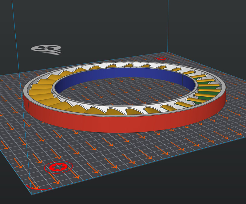
To capture and qualify specimen characteristics, engineers must qualify the entire stroke of the machine, including (Z height) and across both the build plate width (X) and length (Y). Test builds are intentionally built with the maximum number of specimens to maximize the production build area and duration. Builds also often include material capture vessels in each corner of the build plate to capture material that can be analyzed for chemistry after the formation. The red area represents the tool overlap (stitching) area, where multiple tools may affect the manufacturing process. In binder jetting this may mean printhead overlap areas, or nozzle overlaps for redundancy. In photopolymerization this means multiple light engines being used to cover the whole build area.
Once printed, these specimens are then measured for relevant properties, and their mechanical properties are stored in a database.
Once a machine has been qualified, part qualification is performed by printing test specimens inside, next to, or onto a part. Mechanical properties of these specimens must match the material properties of the process database within an agreed on level of tolerance. This type of part acceptance testing will continue during production runs to ensure part consistency.
- Available materials (new materials, multi-material)
- Printable parts (small features, thin walls etc.)
- Quality of parts (material homogeneity, surface profile)
- Whether or not the process requires aids such as supports